First of all, the goal of this post is explaining how you can flash and recover the firmware securely, so you would able to modify their contents without risk to brick the device. In a second part, I will cover how to build software for this device.
Why
IP camera market is growing up market and now you can get powerful HD IP cameras for a few dollars. Mostly cheap cameras are based on HISILICON chip, specifically HI3518 and I'm focusing in this chip because of tools availability (SDK).
The cam
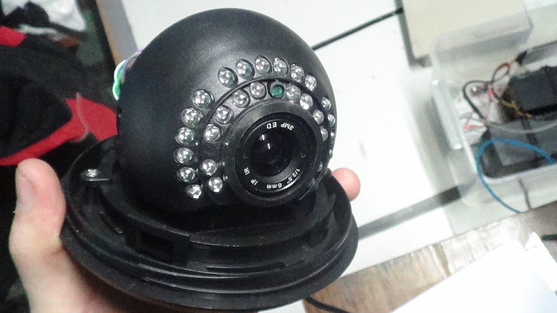
If you want to find this camera, you have to ask for IPC-7060-NS, for example in Alibaba. There are extensive family of solutions based on HI3518, so you could venture discover another camera if you want to.
The board
The board features:
- HI3518C SoC, an ARMv5+DSP chip
- 16 MiB flash memory
- 128 MiB RAM
- Relay for infrared lights
- OV9712d image sensor
and looks like this:
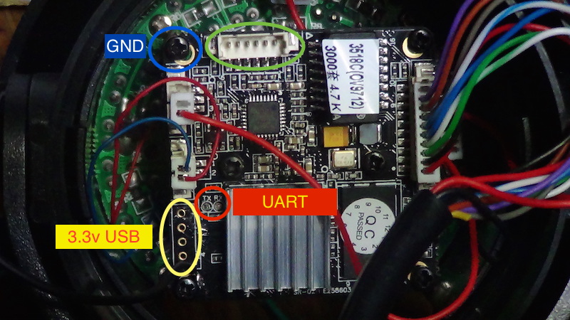
There is a male pin header enclosed in a green circle without a defined function. I was not able to figure out for what it is. On the other hand, it was easy to determine the 4-pins function enclosed in a yellow circle, outer pins are 3.3v and GND, so I asummed it's an USB port for wireless extension (inner pins should be D- and D+). Finally, any corner screw is wired to ground, that's useful to make a serial link.
Serial port (the open door)
Sometimes RX/TX pins are labeled, sometimes they are not. Anyway, you always can see them together near to HI3518 chip (in this picture, the chip is below a heatsink).
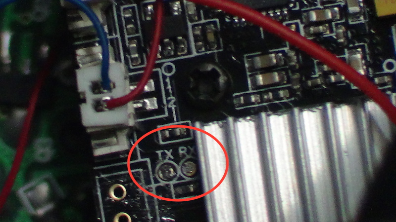
Next, be careful at soldering TX/RX wires, they are close together and almost without space to heatsink. (Third Hand is welcome here)
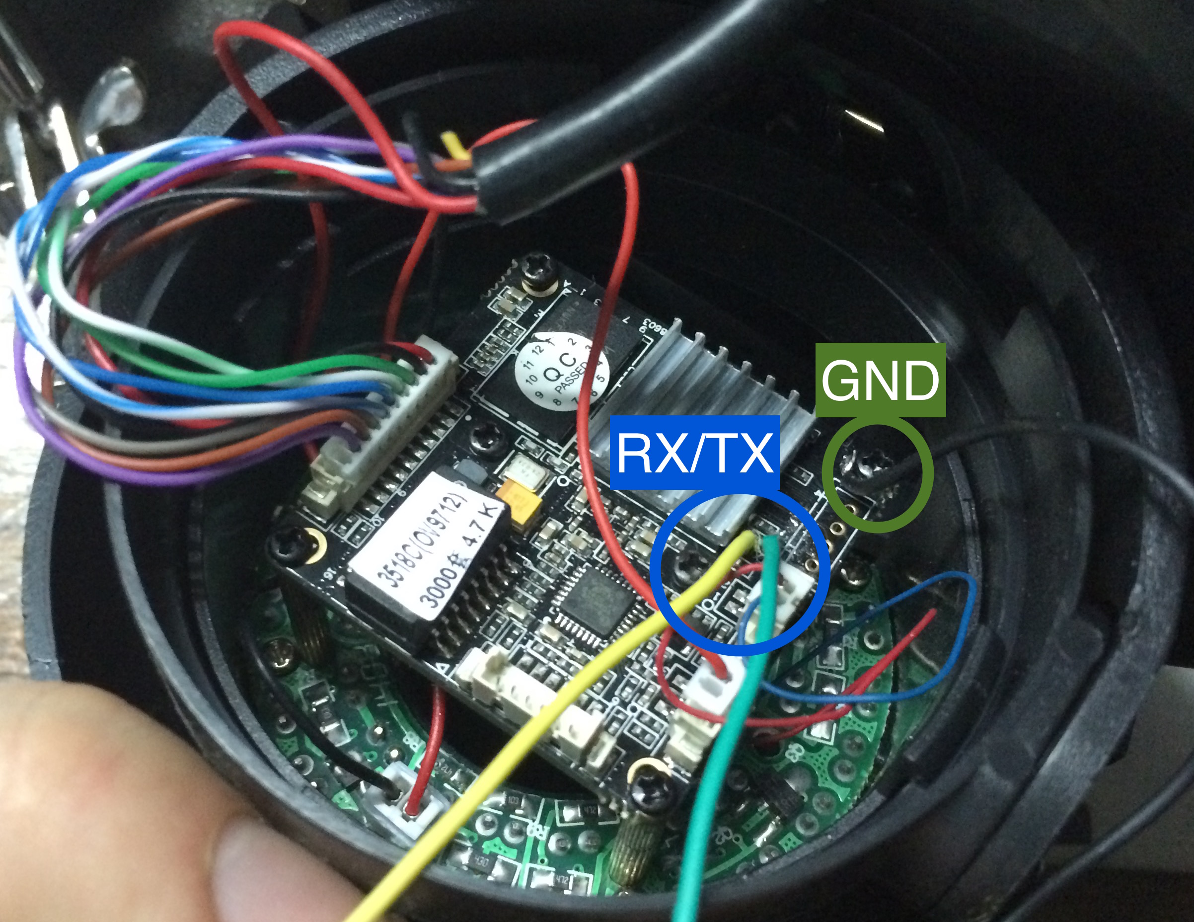
GND can be found in any corner screw. After soldering, you have three wires, RX (yellow), TX (green) and GND (black) for interfacing to USB Serial adapter (PL2303 or FTDI based).
I used a PL2303 based adapter like this (I don't know why my cheap ftdi adapter has stopped to working):
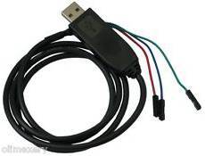
Now, connect wires to USB adapter, board's RX to adapter's TX and so on. Plug adapter to a computer and set speed to 115200 bauds (115200 8N1) without hardware flow control.
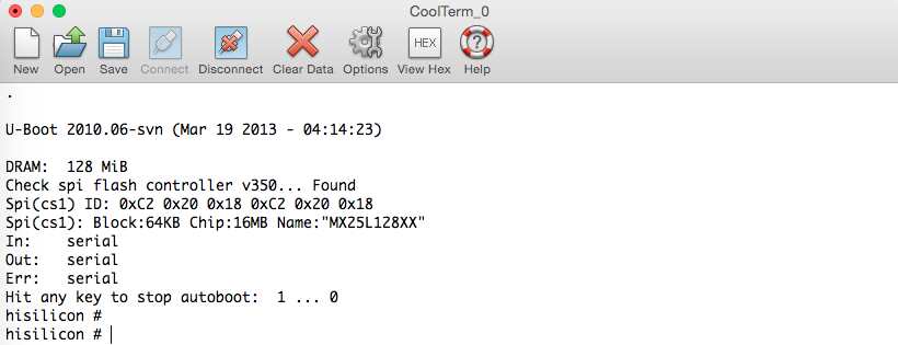
Serial port gives you access to U-boot console [3] at early boot stage
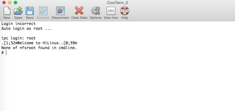
and let you to log in as root without password at last stage. You just have to press enter after to type "root" to gain shell access. Now, you can change the root password by passwd command and, connect to the device via telnet, it's quite more comfortable than UART.
Original flash state back up
Let's see the flash
Flash memory partitions layout
| Address (position) | Name | Size (KiB) | MTD file |
| 0x000000 | Boot | 1024 | /dev/mtdblock0 |
| 0x100000 | Kernel | 2944 | /dev/mtdblock1 |
| 0x3e0000 | Rootfs | 10112 | /dev/mtdblock2 |
| 0xdc0000 | Config | 1280 | /dev/mtdblock3 |
| 0xf00000 | Key | 64 | /dev/mtdblock4 |
Config and Key partitions are used by surveillance software integrated by manufacturer.
Note: How do you get this information? you can figure out flash layout from kernel boot log (dmesg) [1] or from /proc/mtd file.
Copying partitions
You have two ways to do this, via FTP (cam has ftp client) or via NFS. I prefer NFS because a remote directory is seen as a local one and it gives you the power to execute your own programs far away of flash memory (very useful for testing).
How to set up a NFS server? For ubuntu server click here
I'm going to assume that you've exported a directory called /hicam (you can choose another) on NFS server. In the camera side, there is NFS support without lockd, so you should mount NFS directory as follow:
mkdir /mnt/nfs
mount -t nfs -o nolock [SERVER_IP_ADDRESS]:/hicam /mnt/nfs
To avoid data corruption, remount / as a read-only file system.
mount -o remount,ro /Copy the 5 partitions to remote directory
dd if=/dev/mtdblock0 of=/mnt/nfs/mtdblock0 bs=65536
dd if=/dev/mtdblock1 of=/mnt/nfs/mtdblock1 bs=65536
dd if=/dev/mtdblock2 of=/mnt/nfs/mtdblock2 bs=65536
dd if=/dev/mtdblock3 of=/mnt/nfs/mtdblock3 bs=65536
dd if=/dev/mtdblock4 of=/mnt/nfs/mtdblock4 bs=65536
Finally, recover writing ability
mount -o remount,rw /Your back up is done.
Recovering flash state
The bootloader includes a TFTP client to download files into RAM memory and a flash writer to copy data from RAM to flash. To continue, you must set up a TFTP Server.
TFTP Server
How to set up a TFTP server? For ubuntu server click here
If you followed the instructions on the first answer you will have /tftpboot directory. Next, copy all mtdblocks from /hicam to /tftpboot and go to /tftpboot and run:
split -b 5242880 mtdblock2It will split mtdblock2 into two files xaa and xab to avoid a long transfer over tftp. In my experience, files over 5 MiB are a headache for tftp. Now, you have all necessary to begin the recovering.
U-boot
After reset, inmediately send a enter throught serial port. You will get a prompt like this:
hisilicon#In this point, you are able to start the recovering procedure:
Note: Bootloader partition (mtdblock0) is a critical one, so flash it only if you know what are you doing. Try to play with remaining partitions
Set device ip address
set ipaddr [ANY_AVAILABLE_IP_ADDRESS]Set TFTP server address
set serverip [TFTP_SERVER_IP_ADDRESS]don't include brackets
Set up the flash device
sf probe 0Download and store partition 0 (bootloader) image at 0x80008000 in RAM (try to keep the original bootloader)
tftp mtdblock0Erase partition 0's sectors (0x100000 bytes)
sf erase 0 0x100000Copy image from RAM (0x80008000) to Flash (0x0)
sf write 0x80008000 0 0x100000Erase partition 1's sectors (it starts from 0x100000)
sf erase 0x100000 0x300000Download and store partition 1 (kernel) image at 0x80008000 in RAM
tftp mtdblock1Copy image from RAM (0x80008000) to Flash (0x100000)
sf write 0x80008000 0x100000 0x2e0000Got it?, below is the same stuff for remaining partitions
Partition 2 (rootfs)
sf erase 0x3e0000 0xa00000
tftp xaa
sf write 0x80008000 0x3e0000 0x500000
tftp xab
sf write 0x80008000 0x8e0000 0x4e0000
Partition 3 (config)
sf erase 0xdc0000 0x140000
tftp mtdblock3
sf write 0x80008000 0xdc0000 0x140000
Partition 4 (key)
sf erase 0xf00000 0x10000
tftp mtdblock4
sf write 0x80008000 0xf00000 0x10000
Conclusion
After learn this method, you will be able to test another firmware like this guy did [2] without RISK to brick the device. Remember be careful when you replace partition 0, it contains the first program executed after reset. I recommend replacing any partition but the first.